
Description
- Quantity: 1
- High-concerned chemical: LEAD
- Supply Voltage: 9-12V
- Type: Module
- Origin: Mainland China
- Condition: New
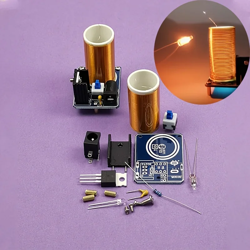
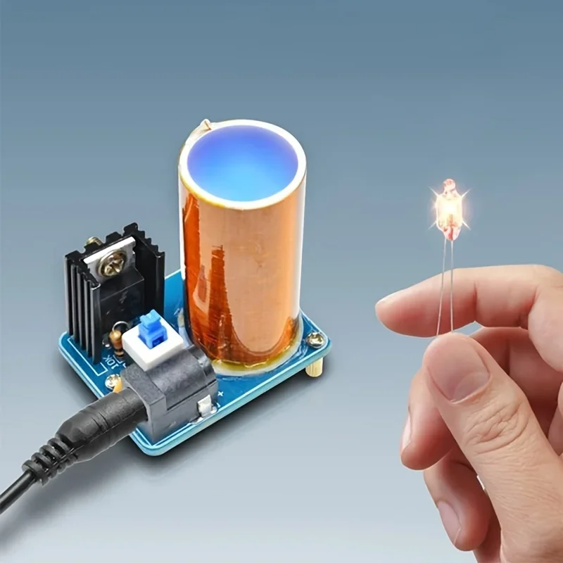
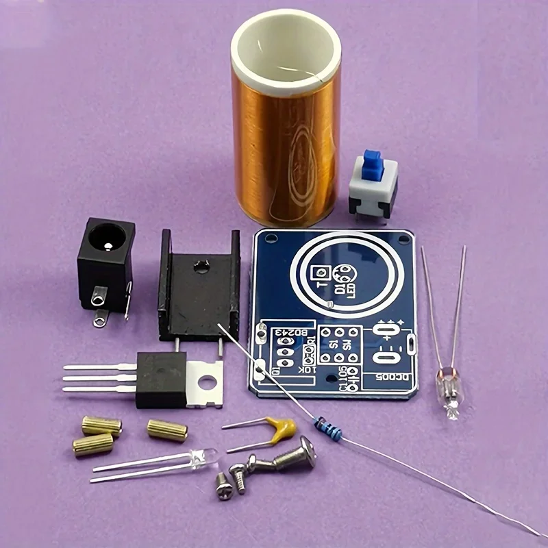
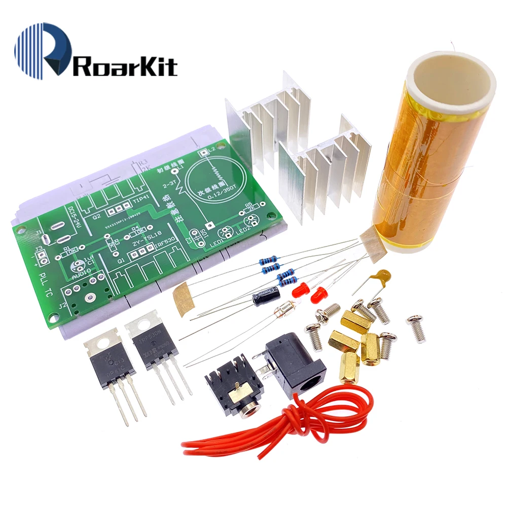
A set of components for a Tesla coil kit that you need to weld and assemble on your own. Tools needed include a soldering iron, glue gun, and water pliers. The input voltage should be between 9-12V; you can start with a 9V battery, but if an arc appears, the working voltage should be 12V.
Remove the protective paint about 3mm before reaching the end of the coil welding wire. This step is crucial. Ensure it is removed. Don't forget.
The 10k resistor should be mounted vertically, and the capacitor should not be polarized. The transistor and heat sink should be screwed and mounted. One end of the secondary coil should be connected to T4 by welding, and the other end should be left hanging.
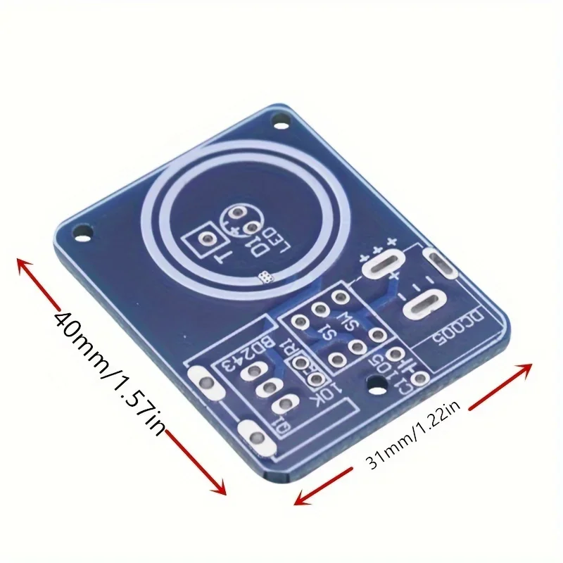
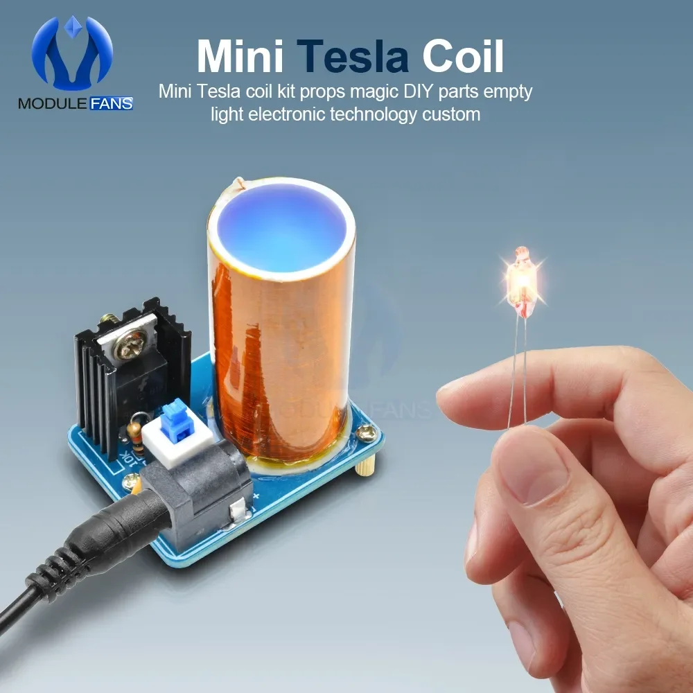
Position the coil precisely between the two white circles and secure it with adhesive. Avoid contact with the coil while the power is on and the heat sink is in use. Keep in mind that prolonged operation may lead to excessive transistor temperature and product damage.

Additional information
| Color | 1 DIY Tesla Coil Kit, 2 DIY Tesla Coil kit |
|---|---|
| Quantity | 1 |
| High-concerned chemical | LEAD |
| Supply Voltage | 9-12V |
| Type | Module |
| Origin | Mainland China |
| Condition | New |
8 reviews for Mini Tesla Coil Kit, BD243, DIY Electronic Project, Hand Solder Practice, No Battery Required, Non-Laser for Hobbyists
Vendor Information


K***v (verified owner) –
Relatively easy to build and a good educational game for my kids.
R***z (verified owner) –
Absolutely love this product! It exceeded my expectations in every way—great quality, easy to use, and delivers real results. Highly recommended to anyone looking for something reliable and effective!
a***r (verified owner) –
While technically not a tesla coil it is a great example of power induction for beginners. Assembly straight-forward and it works as advertised. Just a heads-up you will need some glue not included to secure coil tube to pcb.and a 9-12v supply to power this module
M***n (verified owner) –
Nice kit but quite low power. If you have a better heatsink then it works well on 20v
i***r (verified owner) –
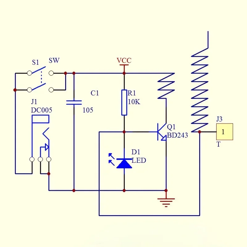
Good quality components. Worked first time for me. Be very careful which way round the led is connected, otherwise the transistor will be damaged by excess negative base-emitter voltage. The circuit diagram is correct, and you can determine the cathode/anode pins from their length. Also, make the mating surfaces of the transistor and the heatsink very flat so that there is the best thermal contact, because this will enable the device to run longer before it overheats.
s***n (verified owner) –
The perfect item for a small DIY construction set, powered by 5V directly from USB, fast delivery, excellent quality 👍👍👍👏👏👏
W***D (verified owner) –
So far so good. Nice little soldering exercise. It worked immediately.
AliExpress Shopper (verified owner) –
Hello, received in France very quickly. Assembly and soldering are easy if you do it in order from the smallest to the largest components. The coil has a direction: the small wire is soldered to the PCB at the bottom and the large one at the top; the large wire needs to be brought back inside. The arc is small, but the phenomenon can be observed starting from 6V. At 12V max, it consumes a little less than 0.5 A. Be careful not to let the assembly run for too long, the transistor heats up very strongly; I personally applied some thermal grease. Good product, very fun.